
Gfci Circuit Breaker Wiring Schematic
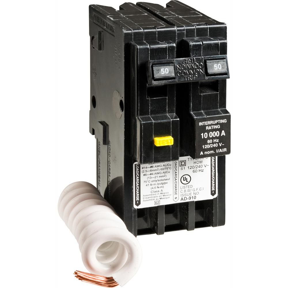
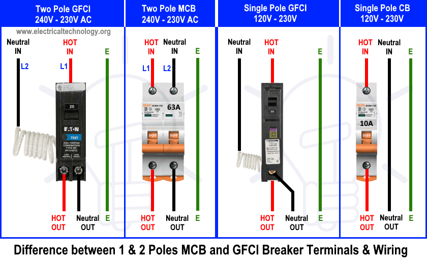
Delmarva, USA. Nov 15, 2009. #6. Square D 2-pole GFI breakers only have a neutral load connection on 50 Amp and smaller units. Their 60 Amp breaker is for 240 Volt loads only. As you have discovered, there are no operational problems with this configuration on 240 Volt loads.
2 Pole Gfci Breaker Wiring Diagram
( See Diagram A ). Replace the receptacle, screw it back into the box, and attach the cover plate. Turn the power back on at the circuit-breaker panel. Plug a clock radio or light into the outlet. Test the GFCI by pressing the Black "Test" button on the outlet.

2 Pole Breaker Wiring
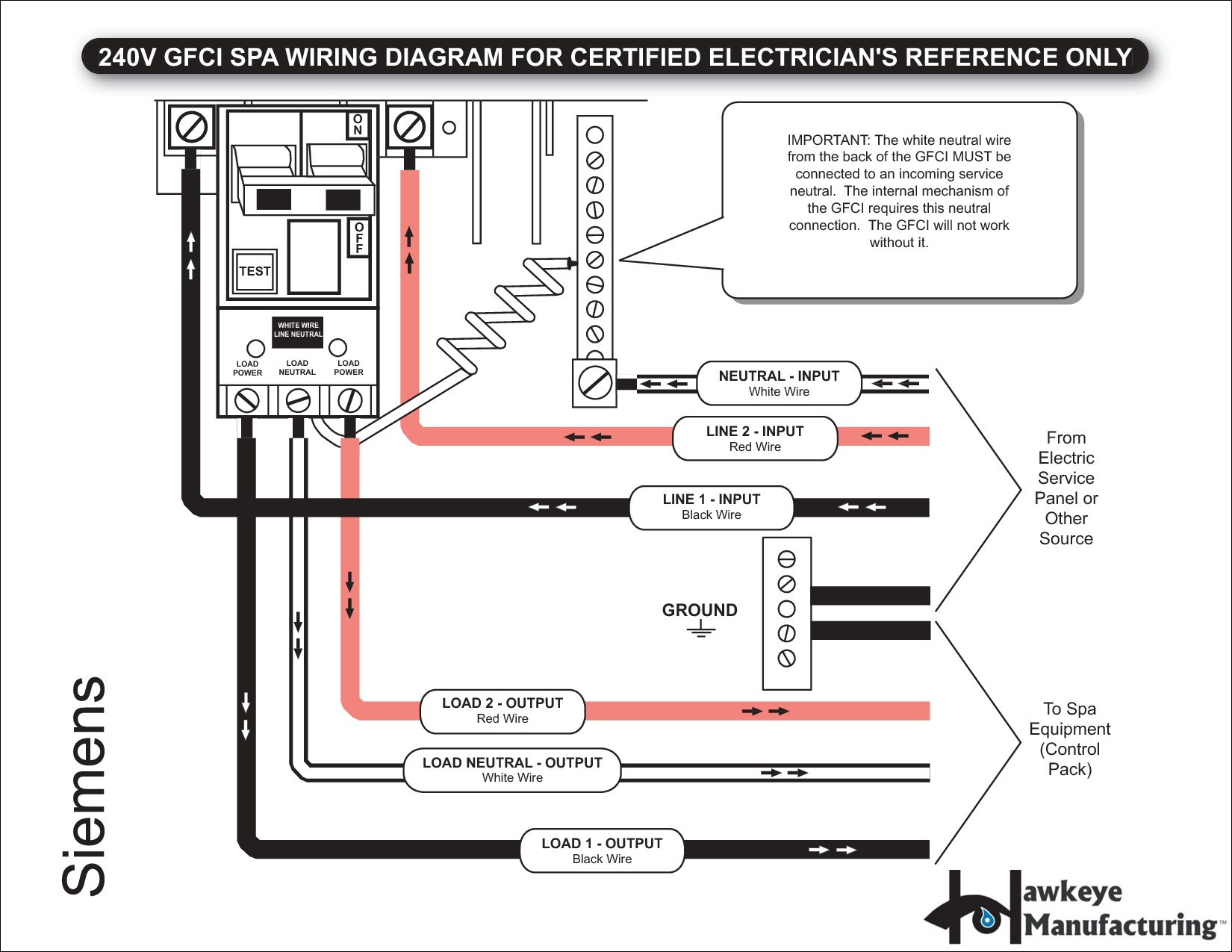
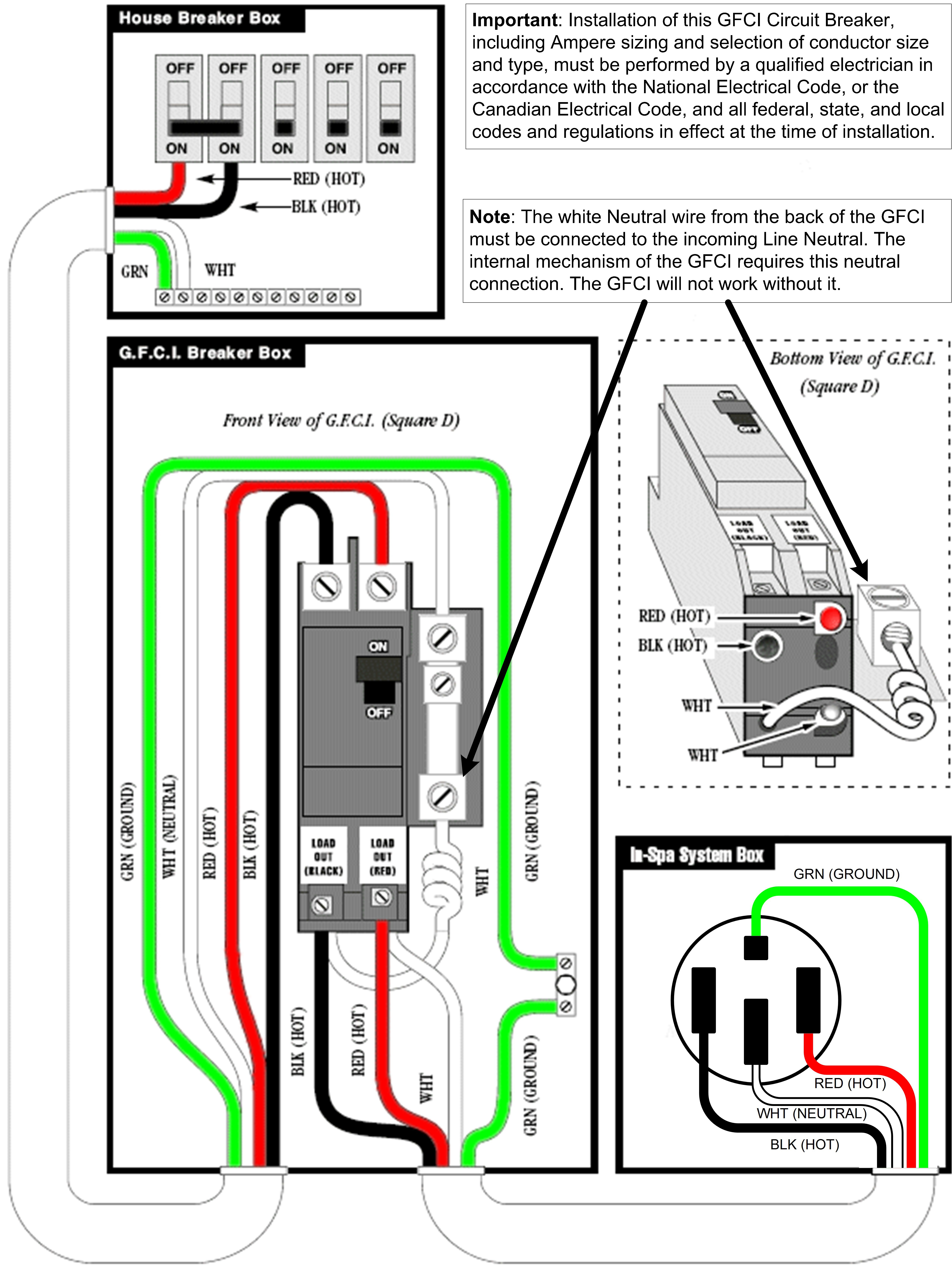
The Siemens 2-pole GFCI circuit breaker can be installed on a 120/240V AC single phase, 3 wire system, the 120/240V AC portion of a 240/120 volt, 3 phase, 4 wire system, or on a 208Y/120 volt, 3 phase, 4 wire system. When installed on these systems, protection is provided for 2 wire, 240V AC or 208V AC circuits; 3 wire, 120/240V AC circuits.

️2 Pole Gfci Breaker Wiring Diagram Free Download Gmbar.co
A 2 pole GFCI breaker is a device that has two separate poles, each with its own internal circuit breaker. The two poles are connected to each other and work together to provide protection against electrocution. When a ground fault or short circuit is detected, the poles will trip and disconnect the power before it can cause any damage.

Bestly Double Pole Gfci Breaker Wiring Diagram
Outline of the Steps The procedure involves the following five steps: Turning off the main panel breaker Testing for power (to ensure it's off) Identifying the GFCI breaker Wiring it (the main part)

60 Amp Double Pole Breaker Wiring
Pierre. is not the white (neutral) conductor that is connected to the 2 pole GFCI breaker necessary for the breaker circuitry to operate properly. The neutral pigtail is not for the operation of the breaker as the GFCI circuit does not need a referance to ground. if there was 120 volts being used then yes as the neutral would have to be.

Double Pole Breaker Wiring
2. Turn "ON" the AFCI/GFCI handle. 3. Press blue test button (F) as shown in Fig.1. The AFCI/GFCI breaker is functioning properly when: 1. The circuit is interrupted. 2. The handle moves to the tripped center position (G) as shown in Fig.1. LEDs (J,M) are used to indicate the last know trip condition. Note: Test every month TROUBLESHOOTING
50 amp gfci breaker wiring diagram
Step #1: Locate the Electrical Service Panel Step #2: Turn Off The Main Circuit Breaker Step #3: Unscrew The Cover Step #4: Test For Power Step #5: Remove The Old Breaker Step #6: Loosen The Screws On The Breaker Step #7: Install The New GFCI Circuit Breaker Step #8: Restore Power Helpful Tips Conclusion Step-by-Step Guide What to Prepare:
Two Pole Gfci Breaker Wiring Diagram Gallery Wiring Diagram Sample
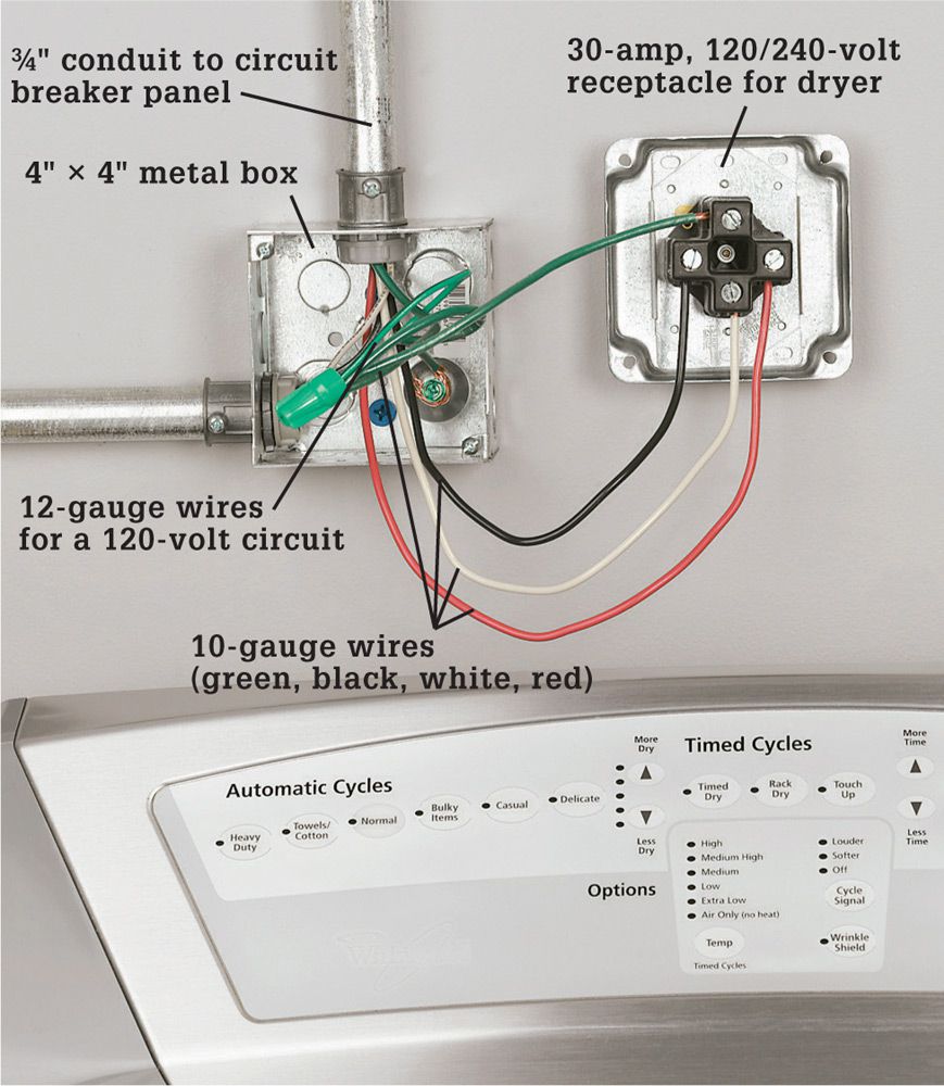
My goal is replace the 2 pole 20 amp breaker in the picture with a 2 pole 20 amp GCFI breaker. From the bottom right knockout hole, the red wire goes to the upper left timer, the blue wire goes to upper right timer and the dark grey wire goes to the upper left timer. Someone previously responded that the dark grey wire is the neutral and should.
Electric Wiring Diagram 2 Pole Gfci Breaker 220 Volt Gfci Breaker Wiring Diagram Electrical
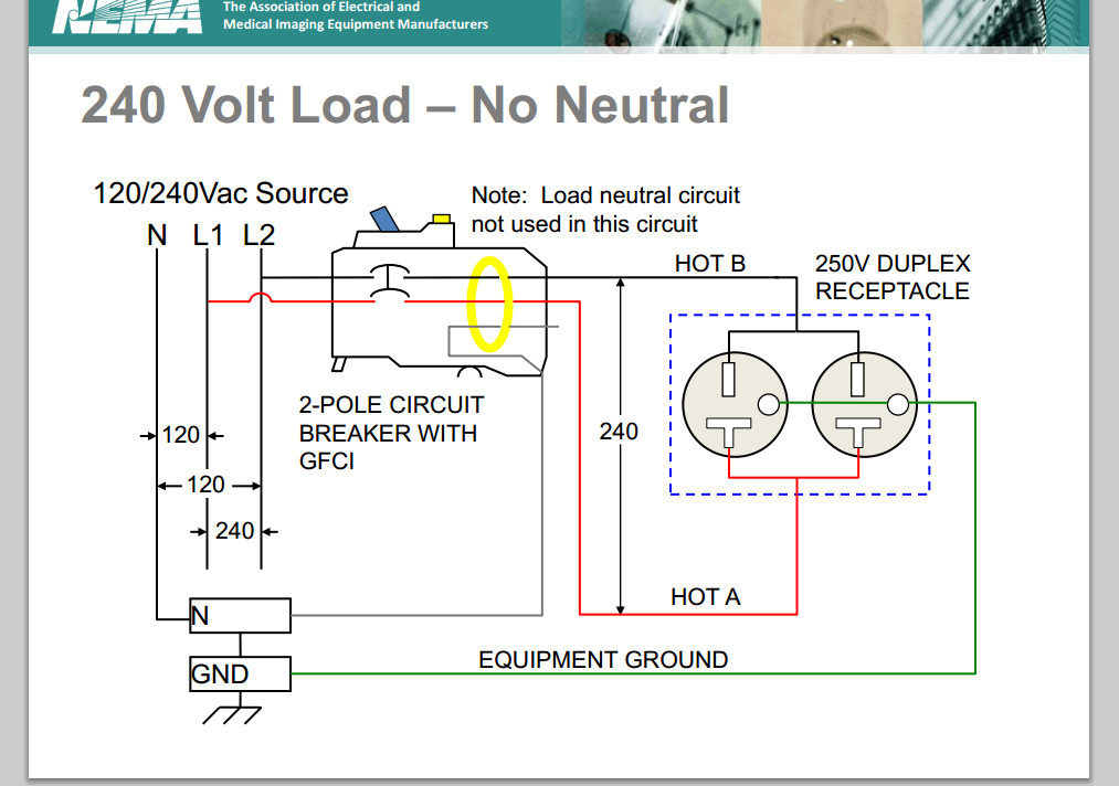
21 1 3 Add a comment 2 Answers Sorted by: 1 No, you do not need a neutral "load" wire if you're running only 240V load. The GFCI will detect any imbalance between the two phases and trip if one occurs. See picture below. The green wire can never be used for anything but a ground. Share Improve this answer Follow answered Apr 17, 2020 at 21:31 JACK
120v Gfci Breaker Wiring Diagram
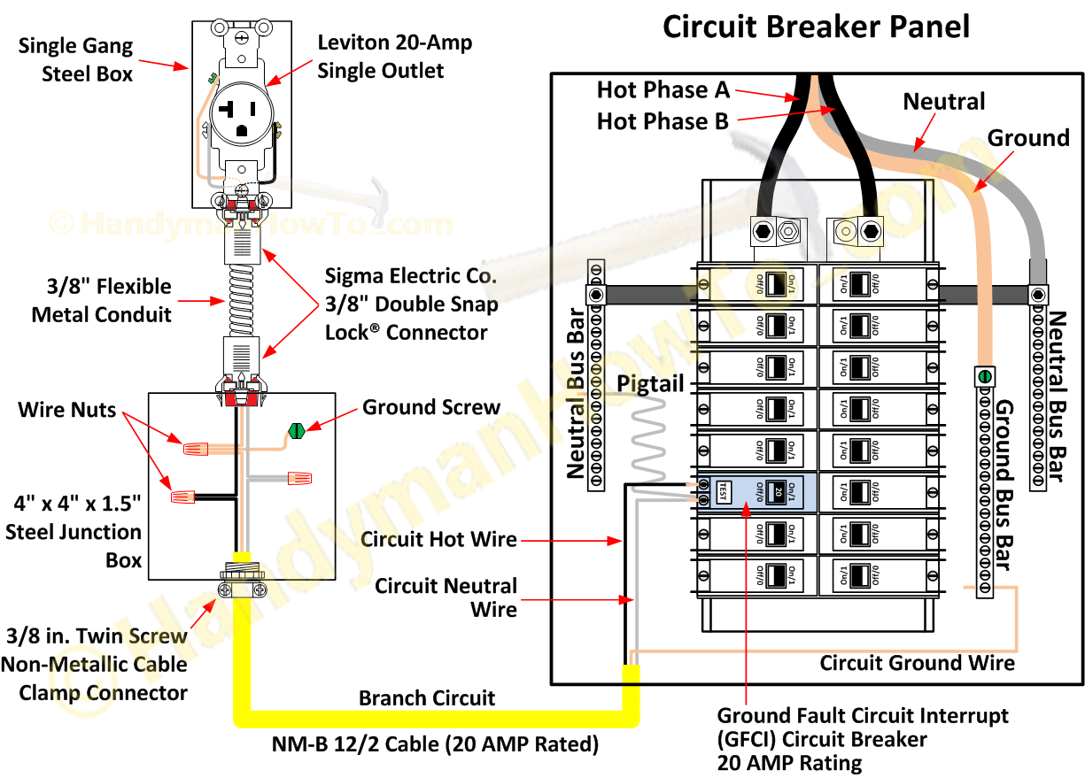
Two-pole GFCI circuit breakers are also available to control two circuits simultaneously. RELATED Wiring a GFCI Circuit Breaker The procedure for wiring a GFCI breaker is similar to how you would attach a regular circuit breaker, except it comes with an extra white wire, typically coiled or pigtailed. Requirements

Seriously! 41+ Little Known Truths on Eaton 50 Amp Gfci Breaker Wiring Diagram? However, because
This instruction sheet contains installation, wiring, testing, and removal information for two-pole (2P) QO/QOB Circuit breakers and Ground Fault.
Wiring 50 Amp Breaker
Press the "Test" button on the breaker, and it should trip, cutting off power to the circuit. Press the "Reset" button to restore power. If the GFCI breaker doesn't trip when the "Test" button is pressed, double-check the wiring and consult the breaker's installation instructions.
220v Gfci Breaker Wiring
***** DISCLAIMER***** Working with electricity can be FATAL Not respecting it.

Carew Wiring Gfci Circuit Breaker Wiring Diagram 2
This circuit breaker wiring diagram illustrates installing a 20 amp circuit breaker for a 240 volt circuit. The 12/2 gauge cable for this circuit includes 2 conductors and 1 ground. The white wire is used for hot in this circuit and it is marked with black tape on both ends to identify it as such. A neutral wire is not used in this circuit.
Two Pole Gfci Breaker Wiring Diagram Gallery Wiring Diagram Sample
The two "hots" that share the neutral must be landed on a 2-pole breaker. This 2-pole breaker assures common maintenance shutoff (an MWBC rule) and that the hots are on opposite 120V poles (a very absolute MWBC rule). Protect a shared-neutral with a 2-pole GFCI breaker. As it happens, they make 2-pole GFCI+breakers, which accept 2 hots and a.