fm transmitter circuit Page 10 RF Circuits Next.gr
A FM transmitter is a device that uses the principles of frequency modulation to broadcast sound supplied at its input. Typical FM transmitter design's usually follow the block diagram below; The signal strength of audio inputs into the transmitter is usually low therefore an amplifier is usually built to bring the signal level up.
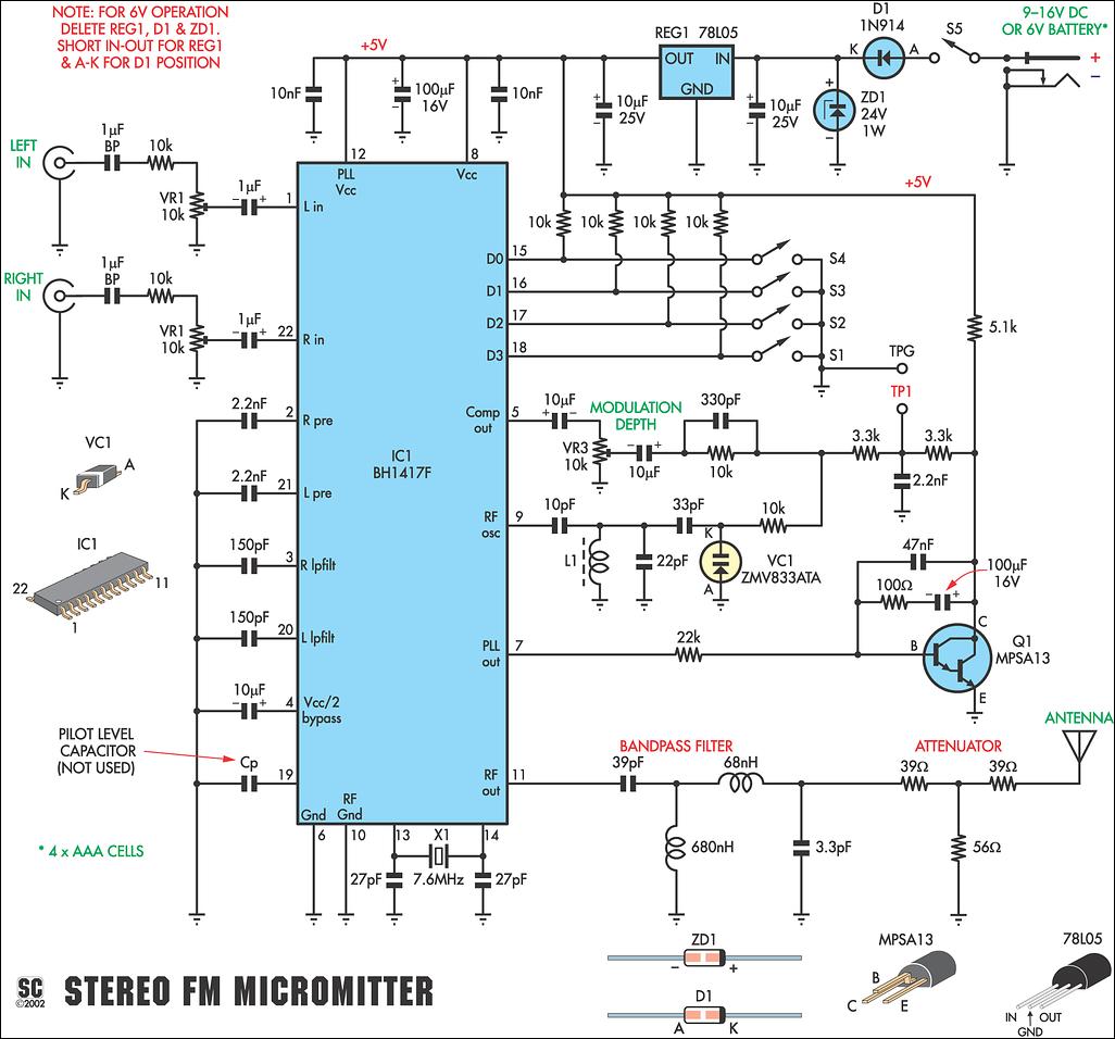
BH1417 PLL Stereo FM Transmitter simple schematic diagram
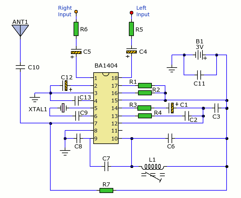
Stereo FM Transmitter using BA1404 IC - This is a stereo FM transmitter circuit using an IC from Rohmm semiconductors named BA1404 - which is a monolithic IC and has a built-in stereo modulator, FM modulator, RF amplifier circuitries. This FM modulator can be operated between 76 to 108Mhz.
Stereo FM Transmitter with BA1404
The transmitter can then be connected to a source of audio, such as a phone or computer, to broadcast music or other audio content. In this project, I have introduced a compact stereo digital FM transmitter circuit that operates in the frequency range of 87MHz to 108MHz. The frequency can be adjusted using two tactile push-buttons, with a 0.
Long Range Rf Transmitter Circuit Diagram
If you need to supply BA1404 FM Transmitter from 12V this simple circuit will do the job. It converts 12V voltage to 3V suitable for BA1404 chip using LM317 voltage regulator. 270 and 390 Ohm resistor determine the output voltage.. BA1404 HI-FI Stereo FM Transmitter broadcasts high quality stereo signal in 88MHz - 108MHz FM band. It can be.

BA1404 3V Stereo FM Transmitter Electronics Infoline Electronics Infoline
Stereo FM Transmitter using BA1404 IC - This is a stereo FM transmitter circuit using an IC from Rohmm semiconductors named BA1404 - which is a monolithic IC and has built in stereo modulator, FM modulator, RF amplifier circuitries.This FM modulator can be operated between 76 to 108Mhz. Stereo FM Transmitter using PLL
FM Stereo Transmitter using BA1404 IC
Info. Contact Data. Shows. Onda Cero is a broadcast radio station from Spain, providing Spanish Talk, National News, Sports Talk & News programs. ------ Shows: Noticias Mediodía, A Ver. See more. News Spanish Sports Talk. 30 tune ins FM 98.0 - 128Kbps. Madrid - Community of Madrid , Spain - Spanish.
Радиопередатчик FM на базе УМЗЧ или готового усилителя НЧ Форум радиолюбителей
An exceptional stereo audio FM wireless transmitter circuit is presented below. The circuit relies upon the IC BA1404 from ROHM Semiconductors. BA1404 is a monolithic FM stereo modulator which includes integrated stereo modulator, FM modulator, RF amplifier circuitry.
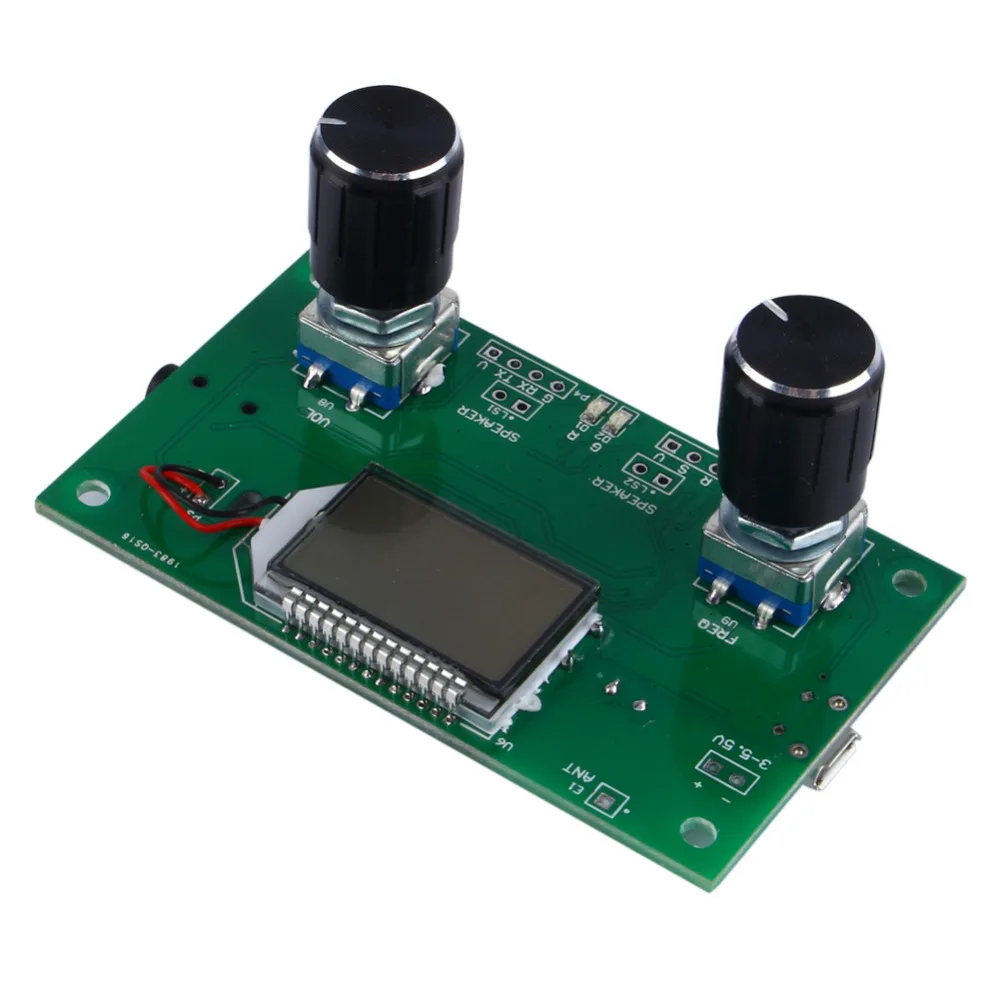
Buy Digital Stereo FM Radio Receiver Module and FM Modulation Phase Locked Loop
Circuit Components: FM Transmitter Circuit Design: Design of Audio Pre-amplifier: Here we are designing a simple single stage common emitter amplifier as the pre-amplifier. a) Selection of Vcc: Here we have selected the NPN Bipolar Junction Transistor, BC109. Since VCEO for this transistor is around 40V, we choose a much lesser Vcc, of about 9V.
FM Stereo Transmitter Communication_Circuit Circuit Diagram
The FM transmitter is a single transistor circuit. In the telecommunication, the frequency modulation (FM) transfers the information by varying the frequency of the carrier wave according to the message signal. Generally, the FM transmitter uses VHF radio frequencies of 87.5 to 108.0 MHz to transmit & receive the FM signal.
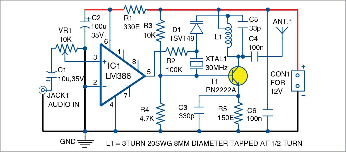
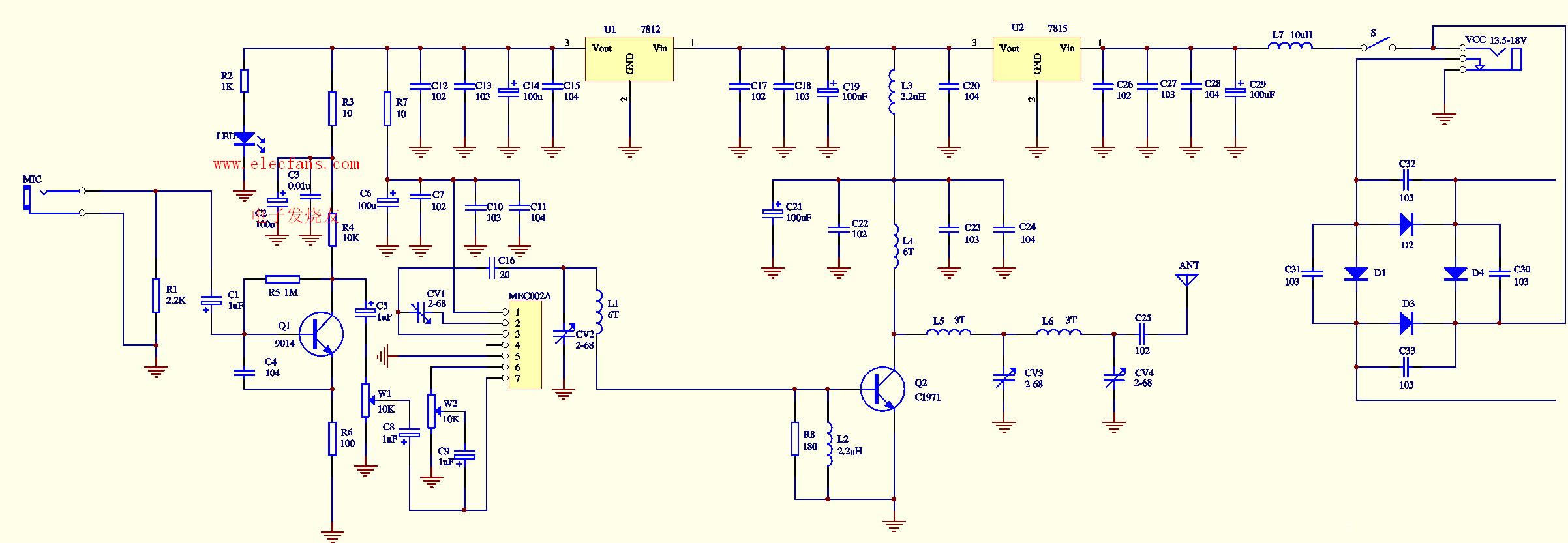
stereo FM transmitter Schematic Power Amplifier and Layout
The circuit is powered by a 9V power supply. Transistor Q1 is a high gain audio amplifier that amplifies the sound detected by the electret microphone. The output of Q1 is fed into the frequency modulating circuit created by transistor Q2, inductor L1, and variable capacitor C5.
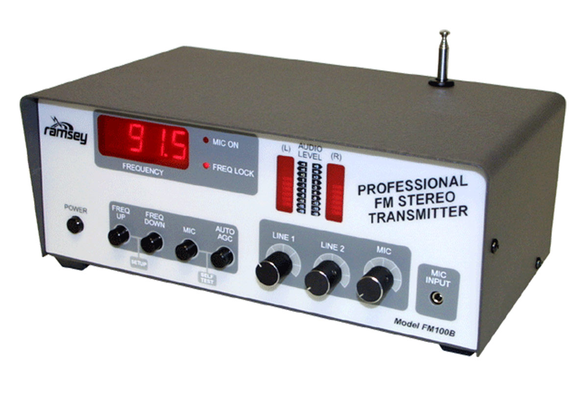
Ramsey FM100BEX FM Transmitter
Working Explanation. Accordingly, the core of the FM stereo transmitter circuit is the BA1404 FM transmitter IC. Generally, the circuit requires just scarcely any expensive parts. However, the information voltage ought to be 1.5V to 3V DC. Moreover, it is recommended to not provide more than 3 volts to the circuit it will harm the IC.
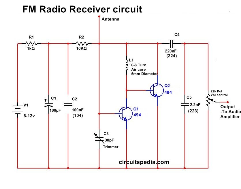
Very simple FM Radio Receiver Circuit circuitspedia
The circuit shown here is of a good Stereo FM transmitter that can transmit high-quality signals up to a range of 70 feet. The circuit is based on BH1417 PLL stereo transmitter IC from Rhom semiconductors.
Audio kit HIFI Stereo Multiplexer for FM transmitter with NJM2035 I.C. circuit
It is a small power fm transmitter that allows data transmission RDS (Radio Data System). Incorporated DSP generates stable stereo signal and attachment RDS data. NS741 applications Wireless microphone Cd and portable mp3 Cell phones NS741 characteristics covered band 76 to 108 MHz stereo modulation RDS transmission Automatic level control
FM stereo transmitter
A simple and high quality FM transmitter circuit designed based on the BA1404 IC .This FM transmitter circuit can be operated from a 3 V battery.

FM Transmitter circuit only with 5 components YouTube
FM — frequency modulation. modulator — a circuit designed to add information to a carrier. modulation index pertains to an FM or PM transmitter. The ratio between carrier-frequency deviation (in hertz) and modulating frequency (also in hertz).
38KHZ_stereo transmitter_fm_ba1404 Suggested PCB mounting stereo FM transmitter with
About The Circuit: These is the exact description of Art Swan, the circuit's Author, "This miniature transmitter is easy to construct and can be picked up on any standard FM receiver. It has a range of up to 1/4 mile or more.